Simulation box
Simulation box
The Maxwell simulation box is divided into mainly two regions, one inner region
for the requested Maxwell propagation and an outer region to simulate the
proper boundary conditions. Later in the input file, the simulation box sizes
refer to the total simulation box which includes the boundary region. The
inner simulation box is defined by the total box size minus the boundary
width. In case of zero boundary condition, there is no boundary region. 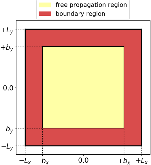
The boundary region can be set up by absorbing boundaries, incident plane waves
or a combination of both. In the latter case, the absorbing boundary region is
the inner boundary region, and the plane waves region is the outer boundary
region. Again, the box sizes are determined by the total simulation box size
and the corresponding boundary width. 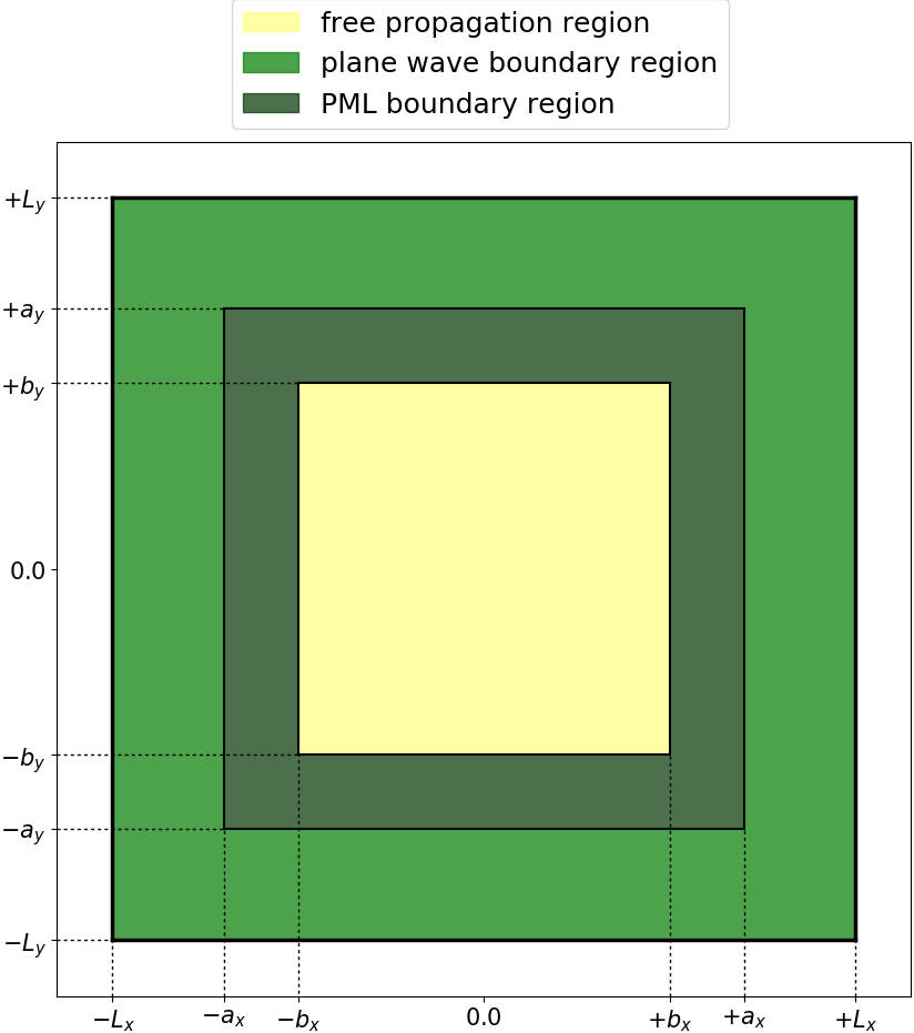
For a given size of the propagation region, the boundaries have to be added to the total box size. The boundary width is given by the derivative order (default is 4) times the spacing. The width of the absorbing boundary region is defined by the variable MaxwellABWidth.
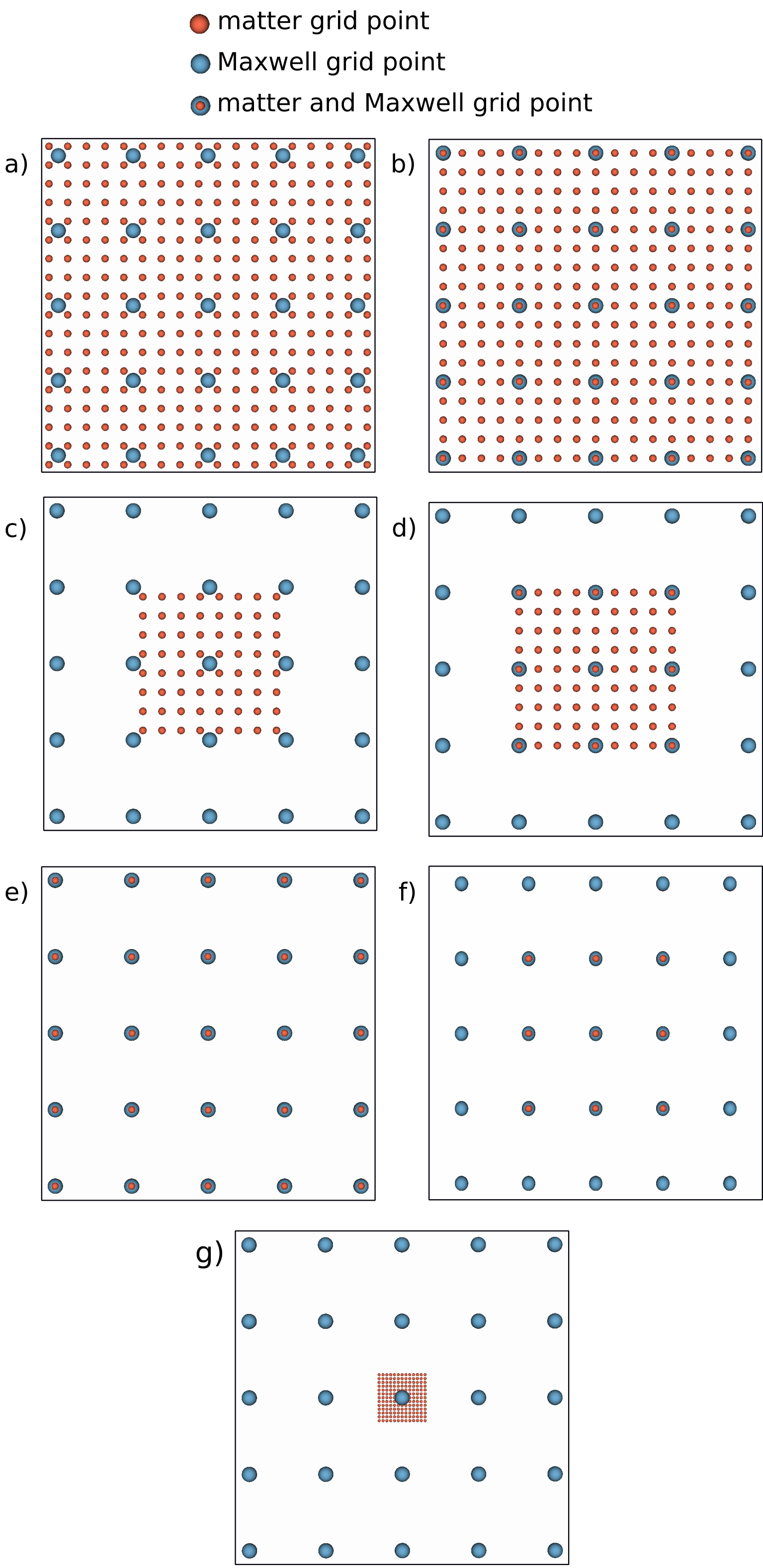
The matter grid is in general located inside the Maxwell grid. There are
several possible types of grids to describe a coupled Maxwell-matter system.
The following figure illustrates some possible cases overlaying Maxwell and matter
grids. In the Octopus code, currently only the types e), f), and g) are
implemented. So the matter box sizes and Maxwell box sizes can be chosen
independently, whereas the spacings of both grids have to be equal and the grid
points have to lie on the top of each other. The only exception is type g),
where the matter grid is much smaller than the Maxwell grid. In this case, the
matter grid size has to be smaller than the Maxwell grid spacing.